HELLO,
HERE I'VE STARTED TO CREATE BLOGS IN THE FIELD OF PHYSICS AND ELECTRONICS........... AS I AM INTERESTED IN SUCH KIND OF INNOVATIVE STUFF, I THOUGHT TO SHARE SOME INFO WITH YOU FRIENDS........
HERE IS SOME INFORMATION REGARDING DC MOTORS.
ALSO PLEASE DO FOLLOW ATTACHED LINKS.
ABOUT D.C MOTORS
In any electric motor, operation is based on simple electromagnetism. A current-carrying conductor generates a magnetic field; when this is then placed in an external magnetic field, it will experience a force proportional to the current in the conductor, and to the strength of the external magnetic field. As you are well aware of from playing with magnets as a kid, opposite (North and South) polarities attract, while like polarities (North and North, South and South) repel. The internal configuration of a DC motor is designed to harness the magnetic interaction between a current-carrying conductor and an external magnetic field to generate rotational motion.

The geometry of the brushes, commutator contacts, and rotor windings are such that when power is applied, the polarities of the energized winding and the stator magnet(s) are misaligned, and the rotor will rotate until it is almost aligned with the stator's field magnets. As the rotor reaches alignment, the brushes move to the next commutator contacts, and energize the next winding. Given our example two-pole motor, the rotation reverses the direction of current through the rotor winding, leading to a "flip" of the rotor's magnetic field, driving it to continue rotating.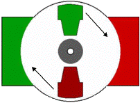 In real life, though, DC motors will always have more than two poles (three is a very common number). In particular, this avoids "dead spots" in the commutator. You can imagine how with our example two-pole motor, if the rotor is exactly at the middle of its rotation (perfectly aligned with the field magnets), it will get "stuck" there. Meanwhile, with a two-pole motor, there is a moment where the commutator shorts out the power supply (i.e., both brushes touch both commutator contacts simultaneously). This would be bad for the power supply, waste energy, and damage motor components as well. Yet another disadvantage of such a simple motor is that it would exhibit a high amount of torque "ripple" (the amount of torque it could produce is cyclic with the position of the rotor). In real life, though, DC motors will always have more than two poles (three is a very common number). In particular, this avoids "dead spots" in the commutator. You can imagine how with our example two-pole motor, if the rotor is exactly at the middle of its rotation (perfectly aligned with the field magnets), it will get "stuck" there. Meanwhile, with a two-pole motor, there is a moment where the commutator shorts out the power supply (i.e., both brushes touch both commutator contacts simultaneously). This would be bad for the power supply, waste energy, and damage motor components as well. Yet another disadvantage of such a simple motor is that it would exhibit a high amount of torque "ripple" (the amount of torque it could produce is cyclic with the position of the rotor). |
 |
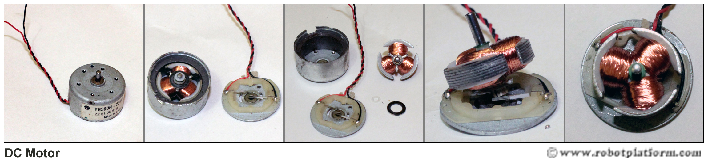
There's probably no better way to see how an average DC motor is put together, than by just opening one up. Unfortunately this is tedious work, as well as requiring the destruction of a perfectly good motor.
Luckily for you, I've gone ahead and done this in your stead. The guts of a disassembled Mabuchi FF-030-PN motor (the same model that Solarbotics sells) are available for you to see here (on 10 lines / cm graph paper). This is a basic 3-pole DC motor, with 2 brushes and three commutator contacts.
|

Let's start by looking at a simple 2-pole DC electric motor (here red represents a magnet or winding with a "North" polarization, while green represents a magnet or winding with a "South" polarization).
Every DC motor has six basic parts -- axle, rotor (a.k.a., armature), stator, commutator, field magnet(s), and brushes. In most common DC motors (and all that BEAMers will see), the external magnetic field is produced by high-strength permanent magnets1. The stator is the stationary part of the motor -- this includes the motor casing, as well as two or more permanent magnet pole pieces. The rotor (together with the axle and attached commutator) rotate with respect to the stator. The rotor consists of windings (generally on a core), the windings being electrically connected to the commutator. The above diagram shows a common motor layout -- with the rotor inside the stator (field) magnets.
So since most small DC motors are of a three-pole design, let's tinker with the workings of one via an interactive animation (JavaScript required):
You'll notice a few things from this -- namely, one pole is fully energized at a time (but two others are "partially" energized). As each brush transitions from one commutator contact to the next, one coil's field will rapidly collapse, as the next coil's field will rapidly charge up (this occurs within a few microsecond). We'll see more about the effects of this later, but in the meantime you can see that this is a direct result of the coil windings' series wiring:
The use of an iron core armature (as in the Mabuchi, above) is quite common, and has a number of advantages2. First off, the iron core provides a strong, rigid support for the windings -- a particularly important consideration for high-torque motors. The core also conducts heat away from the rotor windings, allowing the motor to be driven harder than might otherwise be the case. Iron core construction is also relatively inexpensive compared with other construction types.
But iron core construction also has several disadvantages. The iron armature has a relatively high inertia which limits motor acceleration. This construction also results in high winding inductances which limit brush and commutator life.
In small motors, an alternative design is often used which features a 'coreless' armature winding. This design depends upon the coil wire itself for structural integrity. As a result, the armature is hollow, and the permanent magnet can be mounted inside the rotor coil. Coreless DC motors have much lower armature inductance than iron-core motors of comparable size, extending brush and commutator life.
The coreless design also allows manufacturers to build smaller motors; meanwhile, due to the lack of iron in their rotors, coreless motors are somewhat prone to overheating. As a result, this design is generally used just in small, low-power motors. BEAMers will most often see coreless DC motors in the form of pager motors
Inside an Electric Motor
An electric motor is all about magnets and magnetism: A motor uses magnets to create motion. If you have ever played with magnets you know about the fundamental law of all magnets: Opposites attract and likes repel. So if you have two bar magnets with their ends marked "north" and "south," then the north end of one magnet will attract the south end of the other. On the other hand, the north end of one magnet will repel the north end of the other (and similarly, south will repel south). Inside an electric motor, these attracting and repelling forces create rotational motion. In the above diagram, you can see two magnets in the motor: The armature (or rotor) is an electromagnet, while the field magnet is a permanent magnet (the field magnet could be an electromagnet as well, but in most small motors it isn't in order to save power.
Types of DC Motor
Brushed DC motorBrushed DC motor, or simply a “DC motor” is a classical example of electrical motor. As discussed before, a motor has a rotor and a stator with one of them being a permanent magnet. In a brushed DC motor, the rotor has permanent magnet and the stator has electromagnets. Since the motor needs a way to detect the rotor’s orientation, it uses brushes as a commutator which is a piece of rotor touching the shaft. When the rotor rotates (in turn the brush rotates), it detects the change in orientation and flips the current. DC motors are available in different sizes and at different speeds. Although DC motors run at enough speeds, they are generally useless in robots as they produce the slightest torque. DC motors have only two wires running into them; one for ground and the other for power.
Geared DC motor
As mentioned in previous tutorial, DC motors provide good speeds without enough torque. To overcome this, DC motors are often coupled with gears which provide greater torque, but reducing speed. Normally all our robots would require a geared DC motor to pull the weight of our robot and any additional components placed.
 As you can see in the image, the motor shaft is connected to another bigger gear, which is further connected to a larger gear. As the motor rotates, the rotations per minute (rpm) of Gear1 is lesser than the motor. Gear2 has even less number of rotations per minute. However, each gear increases the torque of overall setup.
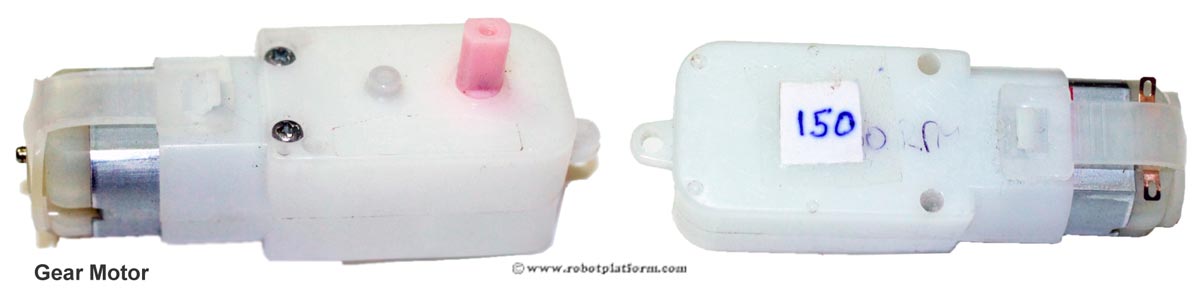
The above image shows a small DC motor fitted with gears. I have marked it as 150 which means the velocity of the motor is 150 revolutions per minute (RPM).
Brushless DC motors
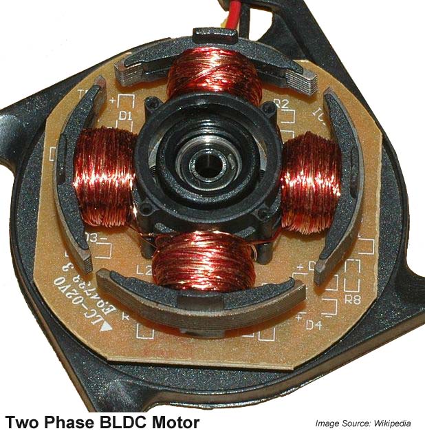
A brushed DC motor uses brushes to detect the change in orientation so that it can flip the current to continue the rotor’s rotation. In a brushless motor, the rotor is made of permanent magnet and the stator is made of electromagnet. To detect a change in orientation, brushless motors generally use Hall Effect sensors to detect the rotor’s magnetic field and consecutively its orientation. Brushless motors are very useful in robots as they are more capable; they provide enough torque, and greater speeds than brushed motors. Brushless motors are expensive due to their design complexity and need a controller to control their speed and rotation.
Servo Motors
Generally known as RC servo motors, these are DC motors coupled with a feedback control circuitry, a gear system to increase torque and a position sensing device (usually a potentiometer). When a signal (pulse) is sent, it moves the motor shaft to a desired position using the position feedback from a potentiometer. Servos do not exhibit continuous rotation, but are limited to a specific range (generally 200° back and forth) and requires us to modify it for continuous rotation. Since servos expect a control signal, there is an additional wire running into the servo which takes control pulses. Hence they have three wires; Ground, Power and Control pulse.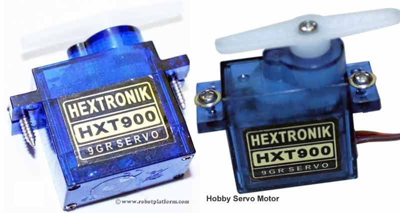
Servos have a wide range of applications in robotics, but require a bit of shrewd programming to make it work. For a detailed explaination, refer Servo Tutorial.
Stepper motors
Stepper motors are brushless motors which divides the rotor’s rotation into discrete number of steps when electrical pulses are applied in an expected sequence. In other words, a brushless motor rotates continuously when voltage is applied across, but a stepper motor breaks it into steps per revolution and jumps each step for a certain pulse. Unlike a servo motor, stepper motor does not require any complex position feedback mechanism; on the torque side, stepper motors are similar to brushed DC motors with less torque. Based on the arrangement of windings inside a stepper motor, it can be classified as Unipolar or Bipolar step motor.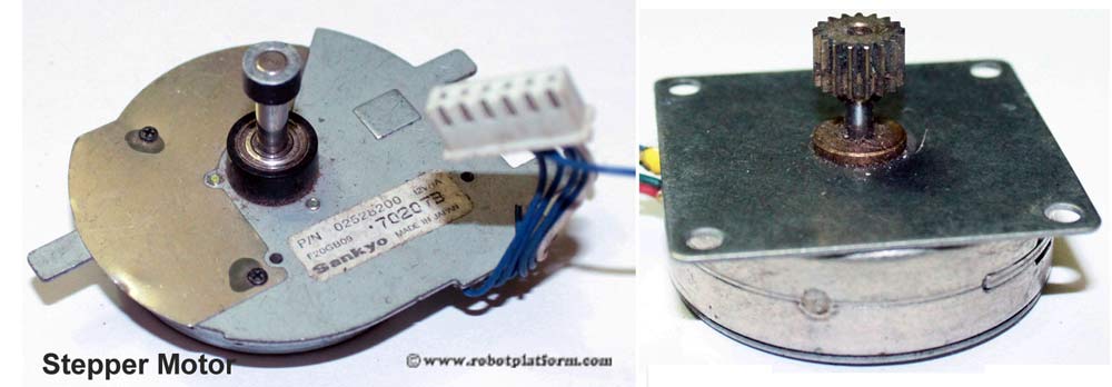
Image shows two different types of stepper motors. The first stepper motor in the image is interesting where the center shaft is fixed and it is the sorrounding body which actually rotates. Second image is of a typical stepper motor which receives pulses and rotates the shaft.
Linear DC motor
Not likely to be used in standard mobile robots, a linear DC motor is a normal DC motor with its stator spread out. To be more specific, a brushed DC motor has a rotor spinning inside a stator; in a classical linear DC motor, the stator is unwrapped and laid out in the form of a track made of flat coils. The rotor rolls over the stator in a straight line.
.
.
.
.
.
.
.
.
. THAT IS ALL I HAD TO SAY ABOUT D.C MOTORS FOR NOW.......... I'LL UPDATE MORE INFO LATER. :).
THANK YOU.
U can write to me at eltonjtd@gmail.com.
--------------------------------------------------------------------------
PHOTO GALLERY....
THESE MOTORS ARE USED IN PREPARING AIRCRAHTS (RC. DRONES).
.jpg)
BRUSHLESS MOTOR ( E.S.C CONTROLLED)
1700 KV.
.jpg)
.jpg)
SERVO MOTOR.... TORQUE - 5 Kgs
plastic geared.
----------------------------------------------------------------------------------------- '
No comments:
Post a Comment